Turbo Tech Part 1: How Turbochargers Work
Many enthusiasts are constantly looking for ways to squeeze more power out of their engines. One way to accomplish this is by providing more air and fuel into each cylinder allowing the potential for more powerful explosions. This can be done several different ways like making the cylinder bigger (larger bore/stroke), keeping valves open longer (camshaft changes), or changing valve sizes to allow more air in. Unfortunately, each of these routes are pretty expensive for the amount of power gained. Forced induction can be a better option. Forced induction generates more air into the engine through compressing the air and doesn’t require costly machine work, engine removal, or extended downtime. This can be accomplished through Supercharging or Turbocharging your car’s engine. But, how does it work? According to Jeremy Clarkson,”A turbo: exhaust gasses go into the turbocharger and spin it, witchcraft happens and you go faster.” While this is completely true, don’t tie those nooses or bring out the heavy stones just yet. Ahead is a basic explanation geared to give insight into this sorcery.
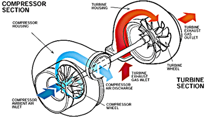
Two critical components to the turbo are the compressor and turbine wheels. These wheels have blades that interact with air as it passes over/through them. Each wheel is encompassed by its own separate housing but is connected with a shaft. The exhaust housing has an inlet connected to outgoing exhaust gasses from the engine. These gasses pass over the blades of the turbine wheel causing it to spin and then exit through a downpipe and out to the rest of the exhaust system. Since this wheel is connected through a shaft to the compressor wheel, it causes the compressor wheel to also spin. The compressor housing has an inlet connected to an intake air filter that sucks in ambient air. As the compressor wheel increases in RPM (it can reach speeds of over 150,000rpm), the air passes through the compressor’s blades and becomes compressed into the housing all the way into each combustion chamber. This creates more forceful combustion and produces higher energy exhaust gasses. These gasses further excite the turbine wheel causing it to spin faster and force the compressor side to suck in more and more air. It keeps spinning and the turbocharger continues compressing. From this explanation, you can see why there is a small delay in experiencing boost after going wide open throttle. You can also see why bigger may not always be better when it comes to selecting the right turbo for your application. Here is a diagram from Garrett to help with the visualization:
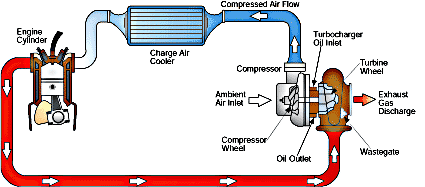
There are components in this forced induction system other than the turbocharger itself. The intake, exhaust, wastegate, intercooler, by-pass or blow-off valve (BPV/BOV), and throttle blade are all worth mentioning. These other components help manage incoming airflow and the amount of pressure the compressor wheel reaches. Upgrading some of these components, along with proper tuning, can yield significant gains on factory turbocharged vehicles. Here is another diagram from Garrett showing how the system is plumbed:
Above is our turbocharged one cylinder. Let’s walk through the travel of the airflow and how each component works.
It all starts with the throttle blade. In our diagram above, this would be located between the “charge air cooler” and the “engine cylinder.” When your foot forces this open, more air comes into the engine. The air mixes with fuel, spark is introduced and the mixture ignites. The spent gasses pass into the exhaust and over turbine wheel causing the compressor wheel to do its thing. This begins the magic mentioned above.
As the throttle blade opens, air comes in through the Intake. Above, this is labeled as “ambient air inlet.” A free flowing intake can help aid the turbo in providing peak power. Also, since colder air is more dense, and in turn can allow the burn of more fuel, the cooler the incoming air, the better. Things like air boxes can be beneficial especially in traffic or other situations where heat soak is prominent. The Mass Airflow Sensor or MAF is also located in this section on vehicles that use a MAF based tuning strategy (Subaru, Mazda, Porsche, GT-R, Mitsubishi). If any changes are made, it’s important to re-calibrate this sensor through proper tuning in order to “see” those changes.
After the air passes through the intake, through the compressor wheel, gets flung outward and compressed, it then travels towards the intake valve of the cylinder. Since the compressor housing is right next to the turbine housing, which is connected to the turbo manifold/header, the air it contains can get pretty warm. Remember, cooler air is better. With that in mind, most turbocharged vehicles have an intercooler (“charge air cooler” in our diagram) on the way to the combustion chamber. There are different intercooler designs but the purpose is all the same; to cool air prior to entering the combustion chamber. This is done by maximizing surface area with plates or fins connected to bars or tubes that the charged air passes through dissipating heat. We’ll talk more about intercooler design and efficiency in another tech post.
The air then goes into the combustion chamber, gets mixed with fuel, ignites, and exits though the exhaust valve, to the header (red section above) and passed the turbine wheel. This continues the spinning and compression hocus-pocus between the two wheels. This could continue until the turbo went beyond its efficiency range and turned into a massive hot air pump (more on efficiency ranges in another post) but the wastegate is there to keep everything in check.
The wastegate can be internal (located inside the turbine housing next to the wheel) or external (mounted on the header or somewhere before the turbine wheel and after the exhaust valve). Both accomplish the same function which is to bleed off excess gasses and slow the turbine wheel. This results in the slowing of the compressor wheel and prevents exceeding boost targets. This is done by actuating (opening) and allowing air through the wastegate instead of having it pass over the wheel. It will then quickly close as to not bleed off too much air and cause a loss in compression in the intake tract (boost). The strategy used to control the wastegate can vary greatly between manufacturers.
The spent gasses then travel out of the turbine housing outlet into the downpipe. Side note: this part of the exhaust is usually called a downpipe because, you guessed it, it’s a pipe that travels downward. As turbo configurations change, the name might also (the 2015+ WRX has a low, front-mounted turbo where a “J-pipe” is the first part of the exhaust connected to the turbine housing outlet). Whatever you call it, it’s the first portion of the exhaust post turbo and is typically the most restricted portion on factory turbocharged vehicles. Upgrading this component, paired with proper tuning, is typically the best bang for your buck modification (although it does vary for platform).
The throttle blade is also the deciding factor in when this witchcraft is halted. When it closes, the BPV/BOV opens allowing air to escape and the intake tract becomes decompressed. This component is typically located between the throttle blade and intercooler. In a system using a BOV, the air is vented to the atmosphere. In a system using a BPV, the air is recirculated into the intake tract. It’s important to retain this re-circulation on MAF based cars no matter how cool it sounds when the air is vented (you can still hear it fine in full re-circulation!). This is because that air has already been measured by the MAF sensor and a certain amount of fuel is injected with the expectation of that air being present. Anytime this air is vented, the car will run rich which can potentially cause issues.
On the next installment we’ll talk about sizing, different specifications, and how to interpret all the numbers associated with a turbocharger. Stay tuned…


I would like to know more about swapping turbo to bigger turbo. What additional required changes need to be done for maximum efficiency? What is the safe zone for the MS3 2.3L engine for example ? Most important – which aftermarket turbo manufacturer would you recommend and why ? Would you recommended to buy a slightly oversized turbo ?
Whenever you are increasing the amount of air being forced into the engine you need to make sure you have the fuel capacity to match. The MS3 Direct Injection system is capable of providing enough fuel for some turbo upgrade, I would recommend checking out a few build threads over on Mazdaspeed Forums to get an idea of required upgrades to support an upgraded turbocharger. I always recommend purchasing the smallest turbo required to reach your power goals. This will ensure better off-throttle response and quicker spool.
Marshall@COBB